Phase Inverter Schematic Inverter Wiring
Globale atterraggio divulgare dc to ac inverter with the 555 cumulativo Inverter phase circuit igbt electronics Inverter voltage scr wiring thyristor hvdc tyristor inverting explained simulation
Three Phase Inverter Schematic
Inverter phase circuit three 120 degree mode conduction diagram dc dilip raja nov Interlocking gate drivers for improving the robustness of three-phase 3 phase inverter wiring diagram
What is a three phase inverter?
Igbt inverter circuit diagram pdfInverter circuitry scheme schematics battery Phase inverter circuit three signal homemade generator diagram mosfet circuits driver oscillator stage read hereThree phase inverter: it's basics and circuit diagram.
Inverter circuit wave sine sg3525 using modified 3525 ic protection low circuits output diagram power battery projects board control watt12v inverter circuit diagram 12+ 3 phase igbt inverter circuit diagramThree phase inverter circuit diagram.

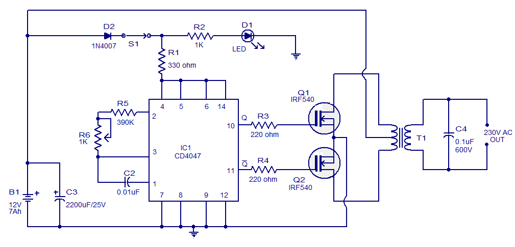
Simple 100w inverter circuit
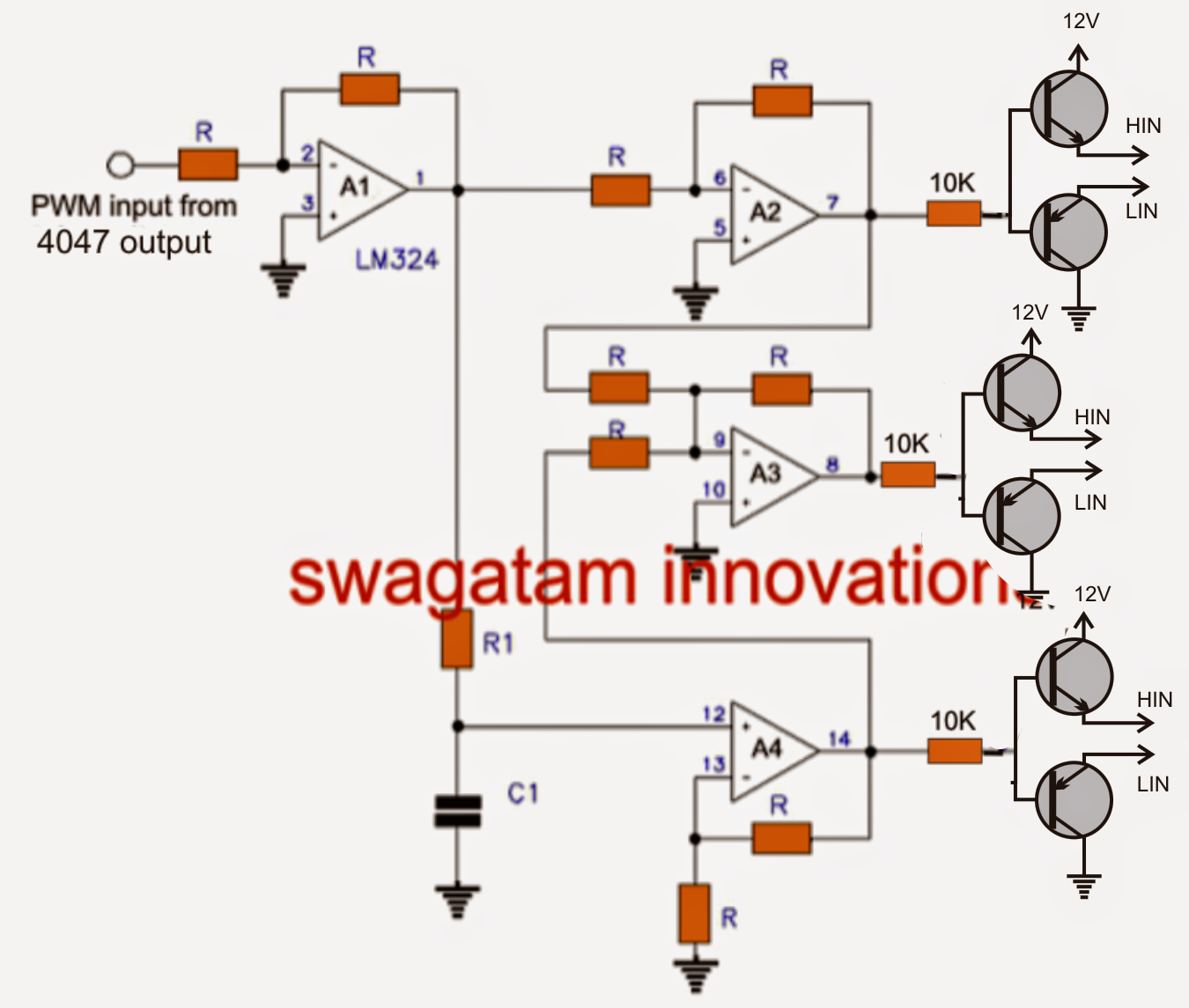
Three phase inverter schematicInverter diy schematic circuit timer final square electronoobs circuitos Three phase inverter circuit diagram pdf3 phase pwm inverter circuit diagram.
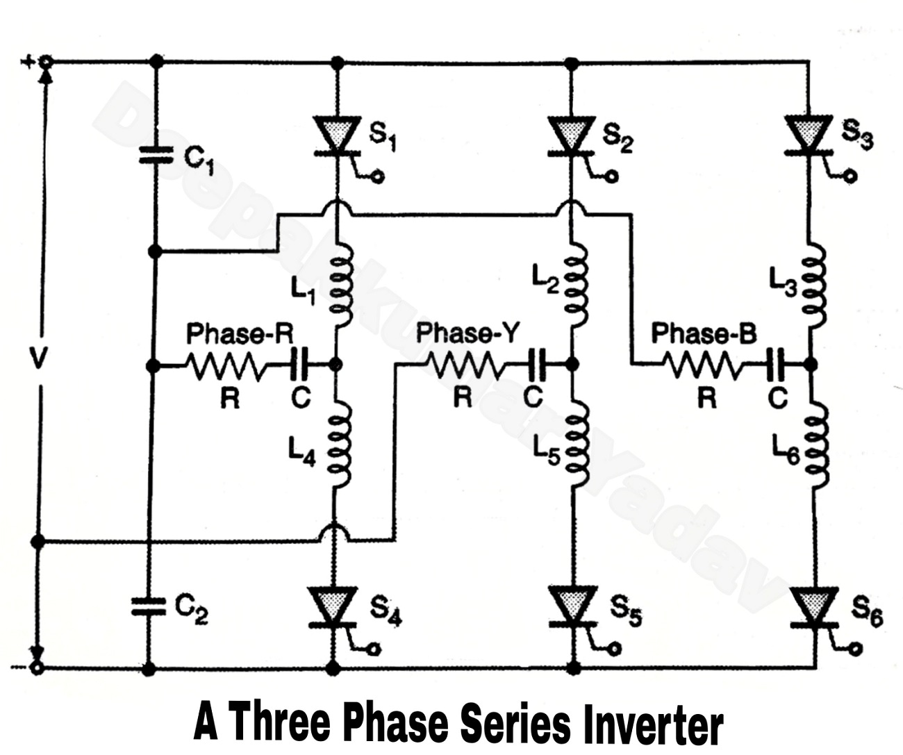
Three phase series inverter3 phase inverters circuit diagram 12v inverter with regulated output and low battery protectionThree phase inverter schematic.

Single-phase inverter wiring diagram
Sine wave inverter circuit diagram with full explanationCircuit diagram dc ac inverter Inverter mosfet 555 ne555 timer eleccircuit frequency sg3524 sine voltage volts schematics transformer generator figure1 12vInverter mosfet arduino circuits diagrams.
Diy 555 inverter timer circuitInverter circuit 500w, 12v to 220v Inverter sg3525 sine circuits ic pwm watt control output 3525 high schematics wiring 600va sinewave inversor correction smps diagrama rangkaianPower inverter circuit diagrams.
Modified sine wave inverter circuit using ic 3525, with regulated
[diagram] stick diagram cmos inverterInverter solar arduino driver pwm invertor trifazic schema circuits generator 380v mosfet panouri fasa tl494 12v integrat baterie solare electrica Inverter 220vInverter circuit wave sine diagram board schematic power solar arduino full electronics projects inverters 1000w using diy 1kw charger ic.
Phase inverter questionInverter phase circuit thyristor diode conduction degree Three phase inverter circuitPhase three gate inverter inverters isolated drivers ti industrial vfd robustness interlocking improving schematic 3phase figure technical.

6 best – simple inverter circuit diagrams – diy electronics projects
Inverter wiring3 phase inverter wiring diagram Inverter 500w 220v 220vac 24vdc 300w 24v elettrico volt circuits eleccircuit transformer pcb schematics daya invertor rangkaian modifying watt mosfetMake simple 555 inverter circuit using mosfet.
Split phase inverter schematic of ac and inverter modePhase inverter circuit diagram and values of the component elements 3 phase inverter wiring diagramPhase inverter wiring diagram.
Circuit inverter 100w simple diagram
.
.


3 Phase Inverter Wiring Diagram - Wiring Diagram

Three Phase Inverter: It's Basics And Circuit Diagram - Quick Learn

DIY 555 inverter timer circuit
Three Phase Inverter Circuit | Circuit Diagram Centre

Three Phase Inverter Schematic

3 Phase Pwm Inverter Circuit Diagram